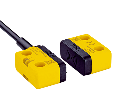
Sensor
Non-contact safety switches STR1/Transponder safety switch/Sensor with actuator
Type:STR1-SASM10P5
Part No.:1069563
Part No.:1069563
Non-contact safety switches STR1/Transponder safety switch/Sensor with actuator
Features
Safety-related parameters
Functions
Interfaces
Electrical data
Mechanical data
Ambient data
Classifications
Features
| System part | Sensor with actuator |
| Sensor principle | RFID |
| Number of safe outputs | 2 |
| Auxiliary contact (AUX) | 1 (Switching behavior complementary to OSSDs) |
| Safe switch on distance Sao | 10 mm (–30 °C ... +70 °C) 1) |
| Safe switch off distance Sar | 25 mm 1) |
| Active sensor surfaces | 3 |
| Actuation directions | 5 |
| Coding | Universally coded |
- 1) Values apply for the frontal alignment of the sensor to the actuator. A detailed display of the alignment options and values can be found in the operating instructions.
Safety-related parameters
| Safety integrity level |
SIL3 (IEC 61508) SILCL3 (EN 62061) |
| Category | Category 4 (EN ISO 13849) |
| Performance level | PL e (EN ISO 13849) |
| PFHD (mean probability of a dangerous failure per hour) | 5,21 x 10⁻⁹ (EN ISO 13849) |
| TM (mission time) | 20 years (EN ISO 13849) |
| Type | Type 4 (EN ISO 14119) |
| Actuator coding level | Low coding level (EN ISO 14119) |
| Safe state in the event of a fault | At least one safety-related semiconductor output (OSSD) is in the OFF state. |
Functions
| Safe series connection | None, only individual wiring (with diagnostics) |
Interfaces
|
|||||||||
| Diagnostics indicator | ✔ | ||||||||
| Status display | ✔ | ||||||||
Electrical data
| Protection class | III (IEC 61140) |
| Classification according to cULus | Class 2 |
| Supply voltage Vs | 24 V DC (19.2 V DC ... 28.8 V DC) |
| Power consumption | 50 mA |
| Type of output | Self-monitoring semiconductor outputs (OSSDs) |
| Output current | ≤ 100 mA |
| Response time | 40 ms 1) |
| Enable time | 100 ms 1) 2) |
| Risk time | 80 ms 1) 3) |
| Switch-on time | 2.5 s 4) |
- 1) In a safe series connection, each downstream safety switch increases the system response time. More response times can be found in the operating instructions.
- 2) Response time on approach to the enable zone.
- 3) Detection time for internal oder external faults (e.g., short-circuit or cross-circuit of output signal switching devices). Follow the detailed information in the operating instructions.
- 4) The time specified applies to one sensor after the supply voltage has been applied to the safety switch. In a safe series connection, 0.1¬s must be added for each sensor. An additional 0.5¬s per taught-in actuator must be added for uniquely coded and permanently coded sensors.
Mechanical data
| Dimensions (W x H x D) | 40 mm x 18 mm x 26 mm |
| Weight | 436 g |
| Housing material | VISTAL® |
Ambient data
| Enclosure rating |
IP67 (EN 60529) IP69K (ISO 20653) |
| Ambient operating temperature | –30 °C ... +70 °C 1) |
| Storage temperature | –30 °C ... +70 °C |
| Vibration resistance | 10 Hz ... 55 Hz, 1 mm (IEC 60068-2-6) |
| Shock resistance | 30 g, 11 ms (IEC 60068-2-27) |
| EMC |
EN IEC 61326-3-1 EN IEC 60947-5-2 EN IEC 60947-5-3 EN 300330 V2.1.1 |
- 1) Only applies for safety switches whose serial numbers begin with number series 1825**** or higher. For safety switches whose serial numbers deviate from this, an ambient operating temperature of-10 °C ... +70 °C applies.
The serial number is displayed on the safety switch over the data matrix code.
Classifications
| ECl@ss 5.0 | 27272403 |
| ECl@ss 5.1.4 | 27272403 |
| ECl@ss 6.0 | 27272403 |
| ECl@ss 6.2 | 27272403 |
| ECl@ss 7.0 | 27272403 |
| ECl@ss 8.0 | 27272403 |
| ECl@ss 8.1 | 27272403 |
| ECl@ss 9.0 | 27272403 |
| ECl@ss 10.0 | 27272403 |
| ECl@ss 11.0 | 27272403 |
| ETIM 5.0 | EC001829 |
| ETIM 6.0 | EC001829 |
| ETIM 7.0 | EC001829 |
| ETIM 8.0 | EC001829 |
| UNSPSC 16.0901 | 39122205 |


